Ubuntu Core: Raspberry Pi 2 or 3
Ubuntu Core
We will walk you through the steps of flashing Ubuntu Core on a Raspberry Pi 2 or 3. At the end of this process, you will have a board ready for production or testing snaps.
User account prerequisites
An Ubuntu SSO account is required to create the first user on an Ubuntu Core installation.
- Start by creating an Ubuntu SSO account
- Import an SSH Key into your Ubuntu SSO account on this page. Instructions to generate an SSH Key on your computer can be found here
Hardware and software requirements
- A Raspberry Pi 2 or 3
- A microSD card
- A monitor with an HDMI interface
- An HDMI cable
- A USB keyboard
- An Ubuntu Core image
Ubuntu Core images
- Raspberry Pi 2
- Rapsberry Pi 3
- Ubuntu Core 16 image for Raspberry Pi 3 (stable) – the older kernel shipped with this image can trigger Wi-Fi issues during first boot, a network cable is recommended.
- Ubuntu Core 16 image for Raspberry Pi 3 (edge) – this image provides reliable Wi-Fi at first boot, but is a daily build and not deemed stable.
Installation instructions
- Copy the Ubuntu Core image on the SD card by following the installation media instructions ›
- Attach the monitor and keyboard to the board. You can alternatively use a serial cable.
- Insert the SD card and plug the power adaptor into the board
First boot
- The system will boot then become ready to configure
- The device will display the prompt “Press enter to configure”
- Press enter then select “Start” to begin configuring your network and an administrator account. Follow the instructions on the screen, you will be asked to configure your network and enter your Ubuntu SSO credentials
- At the end of the process, you will see your credentials to access your Ubuntu Core machine:
This device is registered to <Ubuntu SSO email address>.
Remote access was enabled via authentication with the SSO user <Ubuntu SSO user name>
Public SSH keys were added to the device for remote access.
User login
Once setup is done, you can login with SSH into Ubuntu Core, from a machine on the same network, using the following command:
ssh <Ubuntu SSO user name>@<device IP address>
The user name is your Ubuntu SSO user name, it has been reminded to you at the end of the account configuration step.
First boot tips
- During setup,
console-confwill download the SSH key registered with your Store account and configure it so you can log into the device viassh <Ubuntu SSO account name>@<device IP address>without a password. - There is no default
ubuntuuser on these images, but you can runsudo passwd <account name>to set a password in case you need a local console login.
Install and develop snaps
Your board is ready to have snaps installed — get started with the snap command
You can install a classic Ubuntu environment on top of Ubuntu Core to have a fully-fledged development environment and develop snaps on target ›
From: https://developer.ubuntu.com/core/get-started/raspberry-pi-2-3
Rocket Chat for Raspberry Pi
From: https://github.com/RocketChat/Rocket.Chat.RaspberryPi
•Raspberry Pi is the tiny $30 quad-core computer that revolutionalized affordable servers
•Rocket.Chat is the popular high performance, large capacity, open source web chat platform that rocked the server world
You can now run a private chat server on your Pi for:
•family
•social or hobby group
•sports team
•school
•office

Enjoy Rocket.Chat features including:
•Video and audio chat
•Share photos and voice messages
•Share streaming music and video links
•iOS app for iPhones and iPads
•App for Android phones and tablets
•Desktop app for Windows, MacOSX and Linux
•Operate in 22 different languages
•Multiple Rooms
•Direct Messages
•Private Groups
•Off the record encrypted messages
•Avatars
•Emojis
•Media Embeds
•Link Previews
•Many more …
Background
This project adapts the Rocket.Chat server to run on a Raspberry Pi 3
Installation
You can get a Rocket.Chat server and a mongoDB instance working on your Raspiberry Pi 2 or Pi 3 in a couple of minutes with Ubuntu Core 16!
- Follow these instructions to download and install the Ubuntu Core 16 SD card image for your Raspberry Pi 2 or Pi 3
- Perform
sudo snap install rocketchat-server. This will take a couple of mintues. Wait about 2 minutes after everything has completed. - Then, access
http://<server ip>:3000to access your Rocket.Chat server! Create the first user, which will become the server’s adminsitrator. Have fun!
Put your chat server on the Internet for global access
With your Rocket.Chat server up and running, start another shell – typically (Ctrl-Alt-F2) or (Ctl-Alt-F3).
Login, download and start ngrok (see ngrok.com if you need more information):
curl https://dl.ngrok.com/ngrok_2.0.19_linux_arm.zip -o ngrok.zip unzip ngrok.zip cd ngrok ./ngrok http 3000 Now follow the instruction and give the ngrok link to your friends and family anywhere in the world.
They can access your server via the ngrok link.
Enable https:// support for your domain name
If you have a registered domain name and a static IP address for your Pi, you can expose your server on the Internet with automatic SSL support. See this for instructions on caddy (reverse proxy that is included in the installation snap) configuration: https://rocket.chat/docs/installation/manual-installation/ubuntu/snaps/autossl
HINT: if you want to use the voice and video chat features, make sure you give them the link starting with https://
Make sure you are using a Pi 3 (or Pi 2) with these instructions.
Pi Zero, Pi Model B, Pi Model B+, or even Pi Model A can all run Rocket.Chat; but have different CPU, memory configurations and instruction sets that may require some additional work – see FAQ to work with these Pi s.
Our community members are running Rocket.Chat on EVERY MODEL of Pi ever manufactured – so come over to our friendly community hangout if you get stuck.
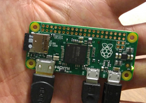
And YES, Rocket.Chat even runs on the $5 Pi Zero! Making it the first-ever $5 private social network that EVERYONE can afford !
Old way of manual installation: On Raspbian only
Make sure you start with a CLEAN INSTALL of Raspbian JESSIE — NOT Wheezy
Get latest Raspian for your Pi
Find download here (this instruction assumes Raspbian Jessie):
https://www.raspberrypi.org/downloads/raspbian/
Use the shell (you do not need the GUI), get the latest fix and updates:
sudo apt-get update
sudo apt-get upgrade
sudo apt-get install git
Get required node and npm
The version of node distributed with Raspian is too old. npm is not included.
The easiest way to get both is to clone from the Meteor universal project.
cd $HOME
git clone --depth 1 -b release-1.2.1-universal  https://github.com/4commerce-technologies-AG/meteor.git
then
$HOME/meteor/meteor -v
At this point, you may encounter a curl execption with ca problem. This is confirmed to be a bug with the latest Debian/Raspbian, and will be fixed in time. Meanwhile, please see FAQ question #1 for a bypass / temporary fix.
Retry the above command after the curl fix.
Download the Rocket.Chat binary for Raspberry Pi
cd $HOME
mkdir rocketchat
cd rocketchat
curl https://cdn-download.rocket.chat/build/rocket.chat-pi-develop.tgz -o rocket.chat.tgz
tar zxvf rocket.chat.tgz
This will download and untar the app in $HOME/rocketchat
Alternatively, you can find the latest release here, and just download it.
Get a compatible MongoDB instance
Current available mongodb versions on Raspbian are too old for Rocket.Chat. Hopefully the situation will change shortly.
Meanwhile, you can use a MongoDB service provider on the Internet. MongoLab offers free sandbox databases that can be used with Rocket.Chat. Create a free account and database here:
Create a user and give it write access to the database. Note the Mongo URL, you will need it next.
Install dependencies and start Rocket.Chat
cd $HOME/rocketchat/bundle/programs/server
$HOME/meteor/dev_bundle/bin/npm install
Next,
cd $HOME/rocketchat/bundle
Type the following ALL on one single line, with spaces to separate the environment variables:
PORT=3000 ROOT_URL=http://localhost:3000 MONGO_URL=mongodb://<user>:<password>@<host>:<port>/dataurlfrommongolabs $HOME/meteor/dev_bundle/bin/node main.js
Wait until the server fully starts. About a minute.
Access your Rocket.Chat server and create the Administrative user
Point a browser on your PC to your Raspberry Pi:
http://rasp pi host IP:3000/
Put your chat server on the Internet for global access
With your Rocket.Chat server up and running, start another shell – typically (Ctrl-Alt-F2) or (Ctl-Alt-F3).
Login, download and start ngrok (see ngrok.com if you need more information):
curl  https://dl.ngrok.com/ngrok_2.0.19_linux_arm.zip -o ngrok.zip
unzip ngrok.zip
cd ngrok
./ngrok http 3000
Now follow the instruction and give the ngrok link to your friends and family anywhere in the world.
They can access your server via the ngrok link.
HINT: if you want to use the voice and video chat features, make sure you give them the link starting with https://
Mobile messaging on phones and tablets
Ask your friends to download the Rocket.Chat mobile app on Android PlayStore or the Apple Appstore for their phone and tablets!
Add your server’s ngrok link to the app, and start mobile messaging one another!
Large capacity server
Do you need to serve hundreds or even thousands of registered users? If so, see how you can setup an inexpensive high capacity Rocket.Chat server on Odroid XU4.
More fun with community contributions
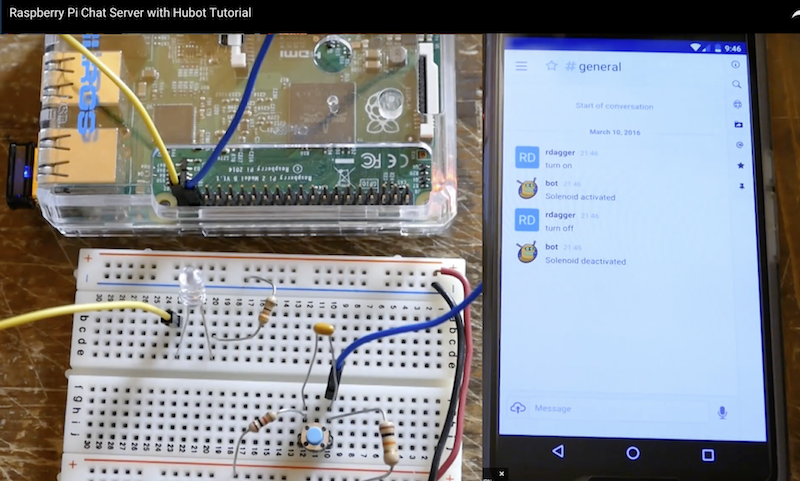
RockOnPi community member @rdagger has contributed this excellent YouTube video on manual installation – just click on picture to watch:
Stuck? Need help?
First, check our list of Frequently Asked Questions to see if your question is already included.
If not, create an issue here: https://github.com/RocketChat/Rocket.Chat.RaspberryPi/issues/new
OR
Come join us at https://demo.rocket.chat/ to get help from friendly RockOnPi community members and Rocket.Chat dev team.
RockOnPi Community meetup 24 x 7
The RockOnPi community gathers at https://demo.rocket.chat/channel/raspberrypi – and talk Pi !!
Makers Ahoy!
Your imagination is your only limit.
Both Raspberry Pi and Rocket.Chat are open source, 100% programmable, 100% Makers-ready!
- get the Raspberry Pi Camera into a Rocket.Chat room
- hook up your home control project to Rocket.Chat
- manage your fleet of drones remotely on the web via RC on Pi
Tell us about your innovative project, or find other collaborators at:
https://demo.rocket.chat/channel/raspberrypi
Support this project
Help us spread the word about this project!
Tell all your Pi and Maker friends! Show off Rocket.Chat at your next meetup!
Tweet about us, or show off Pi with Rocket.Chat on Facebook!
Order a Rocket.Chat sticker for your Mac, tablet, or Pi case!
Where to get the Raspberry Pi server
- Off the shelf at any Microsoft store
- Microcenter
- Frys
- Adafruit
- Sparkfun
- Amazon
- Element 14
- Mercado Livre Brazil
- RS Japan
Where to get Rocket.Chat
Apps for iPhone, iPad, Android, Windows, MacOSX:
Server source code (open source MIT Licensed):
Designing Log Periodic Antennas
By Glen Dash, Ampyx LLC, GlenDash at alum.mit.edu
Copyright 2000, 2005 Ampyx LLC
Lightweight and precise, the log periodic has become a favorite among EMC engineers.
In 1957, R.H. DuHamel and D.E. Isbell published the first work on what was to become known as the log periodic array. These remarkable antennas exhibit relatively uniform input impedances, VSWR, and radiation characteristics over a wide range of frequencies. The design is so simple that in retrospect it is remarkable that it was not invented earlier. In essence, log periodic arrays are a group of dipole antennas of varying sizes strung together and fed alternately through a common transmission line. Still, despite its simplicity, the log periodic antenna remains a subject of considerable study even today.
The log periodic antenna works the way one intuitively would expect. Its “active region,” — that portion of the antenna which is actually radiating or receiving radiation efficiently — shifts with frequency. The longest element is active at the antenna’s lowest usable frequency where it acts as a half wave dipole. As the frequency shifts upward, the active region shifts forward. The upper frequency limit of the antenna is a function of the shortest elements.

Figure 1. Basic arrangement of a Log Periodic Dipole Array (LPDA). From Ref. 1.
Log periodic designs vary, but the one most commonly used for EMC work is the Log Periodic Dipole Array (LPDA) of Figure 1 invented by D.E. Isbell of the University of Illinois. The LPDA we will discuss in this article covers a frequency range of 200 to 1000 MHz. We did not actually build it, but we did simulate its operation on a Method of Moments simulator.
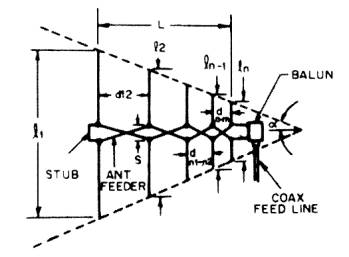
Figure 2: A closer look at the LPDA. Note that adjacent elements are fed out of phase.
The basic geometry is that shown in Figure 2.. Each element is shorter than the element to its left. Ratio of each element to each adjacent element is constant, and is referred to as tau (t). The other critical dimension is the spacing between elements, designated “d” in Figure 2. Distance d1,2 for example, is the distance between the left most element and its nearest neighbor. The distance between two adjacent elements is equal to:
Two factors, tau (t) and sigma (s), are for the most part the only factors we need to consider. Tau, as mentioned, is the ratio of the length of one element to its next longest neighbor. Sigma is known as the “relative spacing constant” and along with tdetermines the angle of the antenna’s apex, a.
Tau and sigma can be selected by using Figure 3 (Ref. 1, 3). For EMC work, we would like to keep the antenna as compact as possible, and we can do so by selecting a low tau. We also would like to keep the gain fairly low so as to avoid too narrow a beam width. We will choose a sigma of .12 and a tau of .8, which should produce an antenna with a gain of approximately 6.5 db over isotropic.
Figure 3: The parameters tau and sigma can be chosen from this graph. We chose a tau of .8 and a sigma of .12 for a predicted gain of 6.5 dBi. The line for optimum sigma is for those designers who want maximum gain. [Ref. 1, 3].
In operation, the LPDA works as follows. Referring to Figure 2, assume that we are operating at a frequency in which the third (middle) element is resonant. Elements 2 and 4 are slightly longer and shorter, respectively, than element 3. Their spacing, combined with the fact that the transmission line flips 180 degrees in phase between elements allows these two elements to be in phase and nearly (but not quite) resonant with element 3. Element 4, being slightly shorter that element 3 acts as a “director” shifting the radiation pattern slightly forward. Element 2, being slightly longer, acts as a “reflector” further shifting the pattern forward. The net result is an antenna with gain over a simple dipole. As the frequency shifts, the active region (those elements that are receiving or transmitting most of the power) shifts along the array.
Having chosen tau and sigma, we simply plug in the numbers. The result is Table 1.
Now comes the tricky part. We have to select the characteristic impedance of the transmission line that feeds the elements, a transmission line that also acts as the boom of the antenna. We will call this transmission line impedance Zb (for boom) and Reference 1 tells us it should be:
This equation deserves some explanation. Zd is the average characteristic impedance of a simple dipole antenna. As stated previously, Zb is the characteristic impedance of the boom, itself a transmission line (referred to as the “antenna feeder” line in Figure 2). Zi is the impedance of the antenna as seen from its input terminals. Those terminals are usually connected to some kind of balun which performs the balanced to unbalanced transformation and steps down the impedance Zi to match the impedance of the signal source (when transmitting) or receiver input (when receiving). The impedance is of this line, referred to as the “coax feed” line in Figure 2, is usually 50 ohms and we will refer to it as Z0.
Figure 4: The antenna we have chosen to model uses two booms acting as a transmission line.
We have chosen to make the antenna elements from 1/4 inch rods. That makes the impedance Zd of the longest element:
Next we choose the spacing between the two booms. The booms will consist of one-quarter inch rods to which the left and right elements are alternately attached (Figure 4). Note that each element is fed 180 degrees out of phase with the elements adjacent to it. For reasons that will become apparent shortly, we will need to choose a relatively high impedance to feed the booms (Zi ). We will choose 200 ohms. This impedance is four times the characteristic impedance of our coaxial line (Z0 = 50 ohms) and is readily produced through the use of a balun with a 2:1 ratio of windings. The spacing between the two booms needs to be (after Ref. 1):
Where:
diam = diameter of each boom in inches.
S = center-to-center spacing between the booms in inches.
We will not be able to hold each element’s ratio of the length to diameter constant since metal stock is not available in all sizes. Instead we will choose diameters which attempt to preserve a length to diameter ratio of approximately 120 (Table 3).
The last design element we will have to design is the terminating stub shown in Figure 1. After Ref. 1, this should be lmax / 8 or 7.4 inches long.
Next we will plug in these numbers into a Methods of Moments program. We will choose EZNEC, being mindful of some its limitations (Table 2). Log periodic antennas can be particularly challenging to model. Through the use of a “Guidelines Check” built into the software, allegiance to the limitations in Table 2 is automatically checked. After some compromises, we settle on the values listed in Table 3 and then press enter to start the simulation.
Figure 5(a) shows the predicted VSWR for our antenna over the frequency range of 200 to 1000 MHz. The VSWR is acceptable below 700 MHz but above that drifts upward. We can make a reasonable guess that the problem at the high end is due to the shortest elements being too long, and so we trim .5 inch off these and run the simulation again. Now the VSWR barely rises above the 1.5:1 range over the entire range of frequencies.
The radiation patterns and gain at 200, 500, 700 and 1000 MHz are shown both as elevation and azimuth patterns in Figure 6. The elevation pattern is the field produced in a plane that slices through the boom of the antenna and is perpendicular to the antenna elements. The azimuth pattern is the field strength in the plane that the antenna elements lie in. Both predict a forward gain that varies from 5 dBi to 7 dBi, reasonably close to our design target of 6.5 dBi.
Our antenna can now be built and should perform well. One drawback to the design, though, is the 200:50 balun that has to be used. Such baluns can introduce losses and may have difficulty in handling the high powers that are sometimes used for susceptibility testing. For this reason, some commercial designs aim at setting the characteristic impedance of the boom at something close to 50 ohms, 75 ohms being a typical target. (Setting the impedance of the boom elements at 50 ohms is not possible when round booms are in use.)
To get such a low impedance, we will have to use thick booms and antenna elements. For the purposes of our example, we will choose .75 inch diameter pipe. First we compute Zd for .75 inch elements:
Then we can calculate the boom center-to-center spacing:
Unfortunately, this log periodic antenna will have to be built to be tested. Its large elements and close spacings (.044 inches between booms) will cause it to exceed the parameters of Table 2. Yes, even in the 21st century there are some things best left to craftspeople.
Those craftspeople also know a few other tricks. One is to dispense with the 50:75 ohm balun and just suffer with a slightly higher VSWR. In order to allow for a balanced to unbalanced transformation, ferrite beads can be slipped over the 50 ohm coaxial cable, producing what is known as a W2DU balun (Ref. 1).
Log periodic antennas are rugged, simple and versatile. They will remain one of the best tools available to the EMC engineer for years to come.
Table 1
The antenna is fed through a 200:50 ohm balun.
Tau = .8 Sigma = .12. Gain = 6.5 dBi.
Alpha = 22.6 degrees. Cot a = 2.4
l1 = 492/(200 MHz) = 2.46 feet = 29.52 inches.
lmin = 492/(1000 MHz) = .492 feet = 5.9 inches.
|
Element |
Formula |
Length (inches) |
|
l1 |
(492/200) ft. |
29.52 |
|
l2 |
l1t |
23.64 |
|
l3 |
l2t |
18.84 |
|
l4 |
l3t |
15.11 |
|
l5 |
l4t |
12.09 |
|
l6 |
l5t |
9.67 |
|
l7 |
l6t |
7.74 |
|
l8 |
l7t |
6.19 |
|
l9 |
l8t |
4.95 |
|
Spacing Between Elements |
Formula |
Distance (inches) |
|
d1,2 |
.5(l1 – l2) cot a |
7.08 |
|
d2,3 |
d1,2 t |
5.64 |
|
d3,4 |
d2,3 t |
4.56 |
|
d4,5 |
d3,4 t |
3.60 |
|
d5,6 |
d4,5 t |
2.88 |
|
d6,7 |
d5,6 t |
2.28 |
|
d7,8 |
d6,7 t |
1.86 |
|
d8,9 |
d7,8 t |
1.49 |
Table 2
EZNEC warns us to observe the following limitations, least it produce untrustworthy answers:
Diameters of all wires should be < .02 l.
Use at least 20 segments per each half wavelength.
Wire spacing should be > .0015 l.
Transmission line spacings should be greater than several wire diameters.
Voltage sources feeding transmission lines should be on a wire 3 segments long and > .02 l.
At their connection point, the ratio of any two wire diameters should be < 2:1.
Table 3: The parameters fed into EZNEC to simulate our antenna. The numbers are in inches.
Figure 5: Figure 5a shows the predicted VSWR for the antenna described in Tables 1 and 3. Shortening the shortest elements of the array by .5 inch each yields the VSWR plot of Figure 5b.
Figure 6: Azimuth and elevation plots for our modified antenna.
References
- The ARRL Antenna Book, The American Radio Relay League, Newington, CT, 1991.
- R. H. DuHamel and D. E. Isbell, “Broadband Logarithmically Periodic Antenna Structures,” 1957 IRE National Convention Record, Part 1.
- R. L. Carrell, “The Design of Log-Periodic Dipole Antennas,” 1961 IRE International Convention Record, Part 1.
http://glendash.com/Dash_of_EMC/Log_Periodic/Log_Periodic.htm
How to install a Raspberry Pi SMS Server
https://www.howtoforge.com/tutorial/how-to-install-raspberry-pi-sms-server/
Before we start
This tutorial will show you how you can set up an SMS server on a Raspberry Pi 2 Model B, running Raspbian.
We will use playsms and smstools. In my example, I have used a Huawei E3131 3G modem.
Raspbian
First we need to download raspbian, you can grab the latest version at https://www.raspberrypi.org/downloads/
Direct url: http://downloads.raspberrypi.org/raspbian_latest
Now we need unzip the file: 2015-05-05-raspbian-wheezy.zip:
unzip 2015-05-05-raspbian-wheezy.zip
You will get a file named 2015-05-05-raspbian-wheezy.img, this file must be written to your micro-sd card.
If you need to know some basics on how to work with raspberry pi, and writing the image to micro-sd, you could start with reading this tutorial:
https://www.howtoforge.com/tutorial/howto-install-raspbian-on-raspberry-pi/
Write image file to micro-sd card, on my PC the micro-sd card is seen as /dev/mmcblk0 on Linux you can use dd:
dd bs=4M if=2015-05-05-raspbian-wheezy.img of=/dev/mmcblk0
- Please note that block size set to 4M will work most of the time; if not, please try 1M, although this will take considerably longer.
- Also, note that if you are not logged in as root you will need to prefix this with sudo.
When the image is written, insert the micro-sd card into your Raspberry Pi, and turn it on.
When the Raspberry Pi is booted, you should see a screen like this, on first startup.
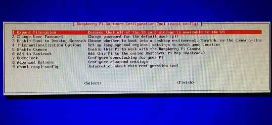
Now I select following options:
1 Expand Filesystem
3 Enable Boot To Desktop/Scratch -> Select Console Text Console, requiring login (default)
8 Advanced Options -> A4 SSH -> Enable
8 Advanced Options -> A0 Update
Finish -> Reboot
Now you can login with following username: pi and password: raspberry.
First we setup the network configuration for our server by editing
sudo nano /etc/network/interfaces
My /etc/network/interfaces file looks like this (change the setup of your needs):
auto lo
iface lo inet loopback

auto eth0
allow-hotplug eth0
iface eth0 inet static
        address 10.255.50.30
        netmask 255.255.255.0
        gateway 10.255.50.1
        dns-nameservers 8.8.8.8 8.8.4.4
Now we restart the network service on the Pi:
sudo /etc/init.d/networking restart
Then we disable DHCP on startup with this command:
sudo update-rc.d -f dhcpcd remove
If you somehow would like to enable it again later, just run following command:
sudo update-rc.d dhcpcd defaults
Now we can use an SSH client such as PuTTY to connect from our PC to the Raspberry Pi.
Now we update raspbian with following command:
sudo apt-get update && apt-get upgrade -y && apt-get dist-upgrade -y
PlaySMS
Download and install playsms 1.1:
sudo -s
apt-get install apache2 libapache2-mod-php5 mysql-server php5 php5-cli php5-mysql php5-mcrypt php5-gd php5-imap php5-curl
php5enmod mcrypt
service apache2 restart
When asked for the new password for the MySQL “root” user, use a strong password, in this example I have used MyP@$$w0rd
Now we can go to http://your-ip, in my case http://10.255.50.30 ,and we will see a page showing: “It Works!”.
cd /tmp/
wget http://downloads.sourceforge.net/project/playsms/playsms/Version%201.1/playsms-1.1.tar.gz
tar -zxf playsms-1.1.tar.gz -C /usr/local/src
ls -l /usr/local/src/
cd /usr/local/src/playsms-1.1/
cp install.conf.dist install.conf
nano install.conf
Copy install.conf.dist to install.conf and edit install.conf
Read install.conf and make changes to suit your system configuration.
I’ve edited the file, so it looks like this:
# INSTALL DATA
# ============


# Please change INSTALL DATA below to suit your system configurations

# Please do not change variable name, you may change only the value

# MySQL database username
DBUSER="root"

# MySQL database password
DBPASS="MyP@$$w0rd"

# MySQL database name
DBNAME="playsms"

# MySQL database host
DBHOST="localhost"

# MySQL database port
DBPORT="3306"

# Web server's user, for example apache2 user by default is www-data
# note: please make sure your web server user
WEBSERVERUSER="www-data"

# Web server's group, for example apache2 group by default is www-data
# note: please make sure your web server group
WEBSERVERGROUP="www-data"

# Path to playSMS extracted source files
PATHSRC="$(pwd)"

# Path to playSMS web files
# note: please make sure your web root path, in this example its /var/www/html
PATHWEB="/var/www/html/playsms"

# Path to playSMS additional files
PATHLIB="/var/lib/playsms"

# Path to playSMS daemon and other binary files
PATHBIN="/usr/local/bin"

# Path to playSMS log files
PATHLOG="/var/log/playsms"


# END OF INSTALL DATA
# ===================
Now Run:
./install-playsms.sh
Press Y if everything looks OK.
Now we want to make sure playsms starts on boot by adding a line into rc.local file.
nano /etc/init.d/rc.local
Add following to the file: /usr/local/bin/playsmsd start
on the bottom of the file (before exit if there’s an exit command).
This way playsmsd will start automatically on boot.
..
/usr/local/bin/playsmsd start
Edit the apache vhost file:
nano /etc/apache2/sites-available/default
My vhost file looks like this:
        ServerAdmin webmaster@localhost

        DocumentRoot /var/www/html/playsms

                Options FollowSymLinks
                AllowOverride None


                Options Indexes FollowSymLinks MultiViews
                AllowOverride None
                Order allow,deny
                allow from all


        ScriptAlias /cgi-bin/ /usr/lib/cgi-bin/
        <directory "="" usr="" lib="" cgi-bin"="">
                AllowOverride None
                Options +ExecCGI -MultiViews +SymLinksIfOwnerMatch
                Order allow,deny
                Allow from all


        ErrorLog ${APACHE_LOG_DIR}/error.log

        # Possible values include: debug, info, notice, warn, error, crit,
        # alert, emerg.
        LogLevel warn

        CustomLog ${APACHE_LOG_DIR}/access.log combined
Now reload the Aapache2 configuration to apply the changes.
service apache2 reload
Then you should be able to access the playsms website at following url:
Go to http://your-ip etc. http://10.255.50.30
You can login with:
username: admin
password: admin
Gateway – SMS Server Tools 3
First we install build tools to build the latest version. Run:
apt-get install build-essential libusb-1.0 libusb-1.0-0-dev
Now I have plugged in the Huawei E3131 modem, and I can see it listed with lsusb:
lsusb
lsusb
Bus 001 Device 002: ID 0424:9514 Standard Microsystems Corp.
Bus 001 Device 001: ID 1d6b:0002 Linux Foundation 2.0 root hub
Bus 001 Device 003: ID 0424:ec00 Standard Microsystems Corp.
Bus 001 Device 004: ID 12d1:14fe Huawei Technologies Co., Ltd.
We would like it to be with ID: 12d1:1506, but it’s detected with 12d1:14fe right now.
To change this, we install usb_modeswitch to the system, you can grab the latest version from here:
http://www.draisberghof.de/usb_modeswitch/#download
cd /tmp
wget http://www.draisberghof.de/usb_modeswitch/usb-modeswitch-2.2.5.tar.bz2
tar jxvf usb-modeswitch-2.2.5.tar.bz2
cd usb-modeswitch-2.2.5
make install
cd /tmp
wget http://www.draisberghof.de/usb_modeswitch/usb-modeswitch-data-20150627.tar.bz2
tar xjvf usb-modeswitch-data-20150627.tar.bz2
cd usb-modeswitch-data-20150627
make install
Now unplug the modem, and plug it in again, then run:
lsusb
 lsusb
Bus 001 Device 002: ID 0424:9514 Standard Microsystems Corp.
Bus 001 Device 001: ID 1d6b:0002 Linux Foundation 2.0 root hub
Bus 001 Device 003: ID 0424:ec00 Standard Microsystems Corp.
Bus 001 Device 006: ID 12d1:1506 Huawei Technologies Co., Ltd. E398 LTE/UMTS/GSM Modem/Networkcard
Now we got the desired mode: 12d1:1506.
Next we proceed with SMS Server Tools 3.
First we download it, then unpack it and install it.
cd /usr/local/src
wget http://smstools3.kekekasvi.com/packages/smstools3-3.1.15.tar.gz
tar -zxvf smstools3-3.1.15.tar.gz
cd smstools3
make
If you see an error like in my case, when you run make:
 make
cd src && make -
make[1]: Entering directory '/usr/local/src/smstools3/src'
Makefile:51: *** recipe commences before first target.  Stop.
make[1]: Leaving directory '/usr/local/src/smstools3/src'
Makefile:10: recipe for target 'compile' failed
make: *** [compile] Error 2
Then do following:
nano src/Makefile
The problem is a missing tab, now look for:
ifeq (,$(findstring DISABLE_INET_SOCKET,$(CFLAGS)))
override LFLAGS += -lsocket -lnsl
endif
And move the line override LFLAGS += -lsocket -lnsl with a TAB
ifeq (,$(findstring DISABLE_INET_SOCKET,$(CFLAGS)))
        override LFLAGS += -lsocket -lnsl
endif
And try to run make again:
make
make install
Now we create some required folders:
mkdir -p /var/log/sms/stats
mkdir -p /var/spool/sms/{checked,failed,incoming,outgoing,sent}
mkdir /var/spool/sms/modem1
chown www-data:www-data -R /var/spool/sms
chmod 777 -R /var/spool/sms
And then move the original configuration file and download a sample from PlaySMS:
mv /etc/smsd.conf /etc/smsd.conf.dist
cd /tmp
wget -c https://raw.githubusercontent.com/antonraharja/playSMS/master/contrib/smstools/smsd.conf
cp smsd.conf /etc/
To make sure I always will use the correct device, I will use a dynamic device file.
Read more about dynamic device files at following URL: http://antonraharja.com/2015/05/14/persistent-paths-for-dynamic-device-file/
nano /etc/udev/rules.d/80-ttyusb-map.rules
ACTION=="add", KERNEL=="ttyUSB[0-9]*", PROGRAM="/etc/udev/rules.d/ttyusb-map.sh %p", SYMLINK+="gsm%c"
touch /etc/udev/rules.d/ttyusb-map.sh
chmod 755 /etc/udev/rules.d/ttyusb-map.sh
nano /etc/udev/rules.d/ttyusb-map.sh
#!/usr/bin/perl -w

@items = split("/", $ARGV[0]);
for ($i = 0; $i < @items; $i++) {
    if ($items[$i] =~ m/^usb[0-9]+$/) {
        print $items[$i + 1] . "\n";
        last;
    }
}
Now unplug, and replug your modem, and it should be located at /dev/gsm*:
ls -l /dev/gsm*
lrwxrwxrwx 1 root root 7 Jul 24 01:39 /dev/gsm1-1 -> ttyUSB0
lrwxrwxrwx 1 root root 7 Jul 24 01:39 /dev/gsmmodem -> ttyUSB0
I made some changes to the file, so here is my config, my modem is located at /dev/gsm1-1 replace that with your location.
# Global configuration

#devices = modem1, modem2
devices = modem1

loglevel = 5

# logfiles
stats = /var/log/sms/stats
logfile = /var/log/sms/smsd.log

# Default queue directory = /var/spool/sms
outgoing = /var/spool/sms/outgoing
checked = /var/spool/sms/checked
failed = /var/spool/sms/failed
incoming = /var/spool/sms/incoming
sent = /var/spool/sms/sent

# do not set report folder, let status report files saved in incoming
#report = /var/spool/sms/report

delaytime = 2
errorsleeptime = 10
blocktime = 180
autosplit = 3
#receive_before_send = yes
incoming_utf8 = yes

# Queue configurations

[queues]
modem1 = /var/spool/sms/modem1
#modem2 = /var/spool/sms/modem2

# Modem configurations

# Modem name: modem1
# Modem type: Wavecom USB
[modem1]
#init = AT+CNMI=2,2,0,1,0;+CMEE=1
#init = AT+CPMS="ME","ME","ME"
device = /dev/gsm1-1
baudrate = 19200
incoming = yes
pin = 3391
report = yes
queues = modem1
decode_unicode_text = yes
cs_convert = yes

# Modem name: modem2
# Modem type: Wavecom USB
#[modem2]
#init = AT+CNMI=2,2,0,1,0;+CMEE=1
#device = /dev/ttyUSB1
#baudrate = 115200
#incoming = yes
#report = yes
#queues = modem2
Restart the SMS Server Tools 3:
/etc/init.d/sms3 restart
Verify if SMS Server Tools 3 is running:
ps ax | grep -v grep | grep smsd
Monitor SMS Server Tools 3 log file:
tail -f /var/log/smsd.log
Login and configure smstools in playsms webpanel
Login to your playsms installation my address is http://10.255.50.30/
Username is admin
Password is admin
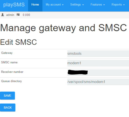
Now go to Settings => Manage gateway and SMSC.
You should see a screen like this:
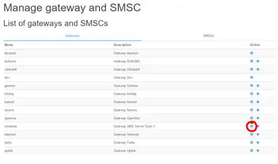
Now click to edit the smstools gateway.
And ensure it’s setup like this:
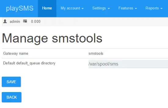
Click Save, and when it’s saved click back.
Now you have to setup the SMSC, so please select the + sign at SMSTools.
You should fill in the SMSC Details like this, in receiver number write your modem phone number.
When you are done click save.
Now go to Settings => Main configuration
And fill following fields:
Default sender ID
Default prefix or country code
And set Default SMSC to smstools, like shown on the image below.
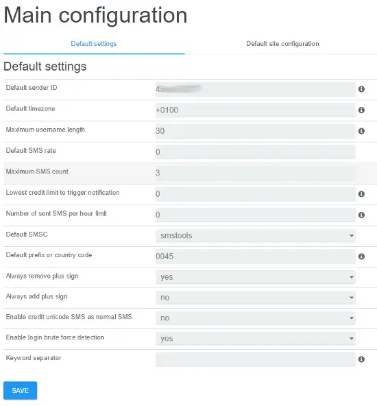
Click save, we are ready to send first SMS.
Send an SMS
Now go to My account => Compose message
Write your cell phone number in Send To, and a message etc. Hello World! in message field, and click send.
If the message get’s queued, you can follow transaction here:
Go to Reports => All sent messages
Incoming messages that are unhandled is kept in sandbox, you will this in Reports => Sandbox
And log if something doesn’t is located in Reports => View log
If you have any trouble with your setup, a good place seek some help is playsms forum.
8-Day Contest Calendar
Reply
Step by Step Kodi Jarvis and Exodus Install
A step-by-step video is a the bottom of the page for a video walk through.
Exodus is Genesis replacement with updated code written by Lambda
Installation like all Kodi add-ons is done by installing a repository and than the add-on.
There is another method to install add-ons which I will list at the bottom of the page,and is were the repository is downloaded and installed manually.
Even though Windows 10 is being used here as an example the same steps will apply to a Windows 7 PC, Kodi box, or other installations.
The download for Kodi can be found here on the Kodi site. https://kodi.tv/download/
Step by Step Kodi Jarvis and Exodus Install
1…
From the main menu go to SYSTEM –> File Manager

2…
Click Add Source

3…
Select None

4…
Type the following URL into the box. http://fusion.tvaddons.ag Be sure it is typed in correctly and click done.

5…
Click in the next box down titled “Enter a name for media source” and type in Fusion.
At his point double check everything has been typed in correctly and click the OK button.

6…
From the main menu click System–>Settings

7…
Add-ons

8…
Install from a zip file

9…
A box will slide open from the side. Click Fusion

10…
xbmc-repos

11…
english

12…
Click repository.exodus.1.0.0.zip It may take a few seconds to install and update.

13…
Go back by using the back arrow and click Install from repository

14…
Exodus repository

15…
Video add-ons
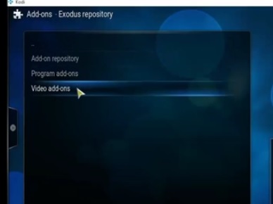
16…
Click Exodus and than install. It will take a few minutes to download and install.

After it is done installing it will be located in the Video–> addons from the main menu.
From: http://www.wirelesshack.org/step-by-step-kodi-jarvis-and-exodus-install.html
How to Turn a Raspberry Pi into a Low-Power Network Storage Device

Mix together one Raspberry Pi and a sprinkle of cheap external hard drives and you have the recipe for an ultra-low-power and always-on network storage device. Read on as we show you how to set up your own Pi-based NAS.
Why Do I Want to Do This?
The benefit of having an always-on network storage device is that it’s extremely convenient to have your data (or backup destination) always accessible to the computers both inside and outside your network. The downside, in most instances, is that you’re consuming a fair amount of power for the convenience.
Our office server, for example, runs 24/7 and consumes almost $200 worth of power a year. A Raspberry Pi-based network storage device on the other hand, consumes about $5 worth of power per year.
We’ll be the first to grant you that a full fledged server is going to have more storage space and the capability to do more work (such as transcoding a multi-terabyte video collection in a reasonable span of time). For most people, however, the principle purpose of having an always-on computer somewhere in the house is to serve as a file server and file backup repository. For such tasks the Raspberry Pi is more than powerful enough and will save you a chunk of change in power use.
What Do I Need?

This tutorial builds on our previous tutorial: The HTG Guide to Getting Started with Raspberry Pi and we’ll assume you’ve already completed that—in other words you already have your Raspberry Pi, got it powered up, hooked to a mouse and keyboard, and you’ve installed Raspbian on it.
In addition to the gear you’ll need from the Getting Started with Raspberry Pi tutorial, you’ll only the following hardware:
- One (at minimum) USB external hard drive for simple network backups and file serving
or
- Two (at minimum) USB external hard drives for local data redundancy
That’s it! If you just want a simple network attached drive, you’ll only need one hard drive. We highly recommend using at least two hard drives in order to allow for local (at the Raspberry Pi) data redundancy. For the purposes of this tutorial we’re using a matching pair of Seagate Backup Plus 1TB Portable External Hard Drives. They’re super small, don’t require an external power source, and were on sale when we were shopping for parts.
You can use any external hard drives you have on hand but it’s ideal to use small low-power drives if possible since the whole theme of the project is to set up a tiny and low-power NAS you can just tuck out of the way and forget about.
Before we continue, there are a couple design choices we made in terms of how we’re configuring our Raspberry Pi NAS that you should be aware of. While most users will want to follow along exactly as we’ve done it, you may wish to tweak specific steps to better fit your needs and how you use the computers on your network.
First, we’re using NTFS-formatted hard disks. Should the Raspberry Pi NAS fail for some reason or we want to quickly copy information over a USB 3.0 connection instead of via the network, having NTFS-formatted disks makes it dead simple to take the portable USB drives we’re using on the NAS build and plug them right into one of the many Windows machines we use every day.
Second, we’re using Samba for our network shares, again because of the convenience of meshing the Raspberry Pi NAS with our predominantly Windows network.
Preparing for and Mounting the External Hard Drives

Once you have gathered up the hardware, followed along with the Getting Started with Raspberry Pi tutorial to get up to speed (and are running Raspian) it’s time to start setting up your Pi as a NAS.
The first order of business is to hook up the hard drives to the Raspberry Pi (or the attached USB hub depending on your configuration and whether or not the hard drives are self-powered or externally powered). Once the hard drives are attached and the Pi is powered up it’s time to get working.
Note: We’re using two hard drives. If you have decided to only use one hard drive simply disregard all the commands in this section intended to mount/modify or otherwise interact with the second hard drive.
We’re going to be doing all of our work within the terminal. As such you can either work directly at your Raspberry Pi using LXTerminal in Raspian or you can SSH into your Raspberry Pi using a tool like Putty. Either way is fine.
Once you’re at the command line the first thing you need to do is to add in support to Rasbian for NTFS-formatted disks. To do so type the following command:
sudo apt-get install ntfs-3g
It’ll take a minute or two for the packages to download, unpack, and install. Once the NTFS package is installed it’s time to look for the unmounted partitions of the attached external hard drives.
sudo fdisk -l
At minimum you should see two disks, if you’ve added in a secondary disk for data mirroring (as we have) you should see three like so: 
The first disk /dev/mmcb1k0 is the SD card inside the Raspberry Pi that houses our installation of Raspbian. We’re going to leave that one completely alone.
The second disk, /dev/sda is our first 1TB external hard drive. The third disk, /dev/sdb is our second 1TB external hard disk. The actual partitions we’re interested in on these two disks are /sda1/ and /sdb1/, respectively. Make a note of the hard drive names.
Before we can mount the drives, we need to create a directory to mount the drives to. For the sake of simplicity we’re going to simply make directory called USBHDD1 and USBHDD2 for each drive. First we have to make the drives. At the command line enter the following commands:
sudo mkdir /media/USBHDD1sudo mkdir /media/USBHDD2
After you’ve created the two directories, it’s time to mount the external drives to each location. Again at the command line enter the following commands:
sudo mount -t auto /dev/sda1 /media/USBHDD1sudo mount -t auto /dev/sdb1 /media/USBHDD2
At this point we have the two external hard drives mounted to the USBHDD1 and USBHDD2 directories, respectively. It’s time to add in a specific directory to both drives to hold our shared folders (for the sake of keeping things tidy and compartmentalizing our work on the drives). Enter the following commands:
sudo mkdir /media/USBHDD1/sharessudo mkdir /media/USBHDD2/shares
Now it’s time to install Samba so we can access the storage from elsewhere on the network. At the command line enter:
sudo apt-get install samba samba-common-bin
When prompted to continue type Y and enter. Sit back and relax as everything unpacks and installs. Once the Samba package finishes installing, it’s time to do a little configuration. Before we do anything else, let’s make a backup copy of the Samba configuration file in case we need to revert to it. At the command line, type the following command line:
sudo cp /etc/samba/smb.conf /etc/samba/smb.conf.old
This simply creates a backup of the configuration file with the filename smb.conf.old and leaves it in the same directory as the original configuration file.
Once we’ve created the backup it’s time to do some basic editing in the Samba config file. Type the following at the command line:
sudo nano /etc/samba/smb.conf
This will open the nano text editor and allow us to make some simple changes. If this is your first time using nano, we would strongly suggest checking out The Beginner’s Guide to Nano, the Linux Command-Line Text Editor. You should see something like the following in your terminal window:

Nano is completely keyboard controlled, use the arrow keys to move the cursor to the location you want to edit. As you click down through the configuration settings, you’ll see a few worth making note of or changing.
The first is the workgroup identifier, by default workgroup = WORKGROUP. If you’re using a different name for your home workgroup, go ahead and arrow over to change that now, otherwise leave it as the default.
Our next stop is to turn on user authentication for our samba storage, otherwise anyone with general access to our network (like guest Wi-Fi users) will be able to walk right in. Scroll down in the Samba config file until you get to the section that reads:

Remove the # symbol from the security = user line (by highlighting it with the cursor and pressing delete) to enable username/password verification for the Samba shares.
Next, we’re going to add an entirely new section to the configuration file. Scroll all the way down to the very bottom of the file and enter the following text:
[Backup]

comment = Backup Folder

path = /media/USBHDD1/shares

valid users = @users

force group = users

create mask = 0660

directory mask = 0771

read only = no
Note: Whatever you put in the brackets in the top line is going to be the name of the folder as it appears on the network share. If you want another name other than “Backup” now is the time to edit it.
Press CTRL+X to exit, press Y when asked if you want to keep changes and overwrite the existing configuration file. When back at the command prompt enter the following command to restart the Samba daemons:
sudo /etc/init.d/samba restart
At this point we need to add in a user that can access the Pi’s samba shares. We’re going to make an account with the username backups and the password backups4ever. You can make your username and password whatever you wish. To do so type the following commands:
sudo useradd backups -m -G userssudo passwd backups
You’ll be prompted to type in the password twice to confirm. After confirming the password, it’s time to add “backups” as a legitimate Samba user. Enter the following command:
sudo smbpasswd -a backups
Enter the password for the backup account when prompted. Once you have created the user account and password you do not need to restart the Samba daemon again as we’ve already instructed it to be on the lookout for authenticated users. We can now hop onto any Samba-capable machine on our network and test connectivity to the network share.
From a nearby windows machine we opened up the Windows file explorer, clicked on Network, confirmed that the hostname RASPBERRYPI was in the WORKGROUPS workgroup and clicked on the shared folder Backups:

When prompted, enter the credentials you created in the previous step (if you’re following along line for line, the login is backups and the password is backups4ever).
Once your credentials are accepted, you will be treated to an empty folder as there isn’t anything in the share yet. To double check everything is working smoothly, let’s create a simple file from the computer we tested the connection with (in our case, the Windows 7 desktop). Create a txt file like so:

Now, from the command line we have been working all this time, let’s check to see if the file we created on the Windows desktop appears properly within the share directory we created. At the command line type the following command:
cd /media/USBHDD1/sharesls

hello-is-it-me-you-are-looking-for.txt is in the directory; our simple shared directory experiment is a success!
Before we leave this section of the tutorial, we only have one more thing to do. We need to configure our Pi so that when it restarts it will automatically mount the external hard drives. To do so we need to fire up the nano editor and make a quick edit. At the command line type:
sudo nano /etc/fstab
This will open up the file systems table in nano so we can add a few quick entries. Within the nano editor add the following lines:
/dev/sda1 /media/USBHDD1 auto noatime 0 0/dev/sda2 /media/USBHDD2 auto noatime 0 0
Press CTRL+X to exit, press Y to save, and overwrite the existing file.
If you’re only using a single hard drive for simple network sharing with no redundancy, then that’s it! You’re all done with the configuration process and can begin enjoying your ultra-low power NAS.
Configuring Your Raspberry Pi NAS for Simple Data Redundancy

So far our Raspberry Pi NAS is hooked up to the network, file transfer works, but there’s one glaring thing missing. That secondary hard drive is configured but sitting entirely idle.
In this section of the tutorial we’re going to use two simple but powerful Linux tools, rsync and cron, to configure our Raspberry Pi NAS to perform a nightly data mirror from the /shares/ folder on the primary drive to the /shares/ folder on the secondary drive. This isn’t going to be a real time RAID-like data mirroring, but a daily (or semi-daily) data backup to the secondary drive is a great way to add another layer of data security.
First, we need to add rsync to our Rasbian installation. If this is your first time using rsync and you’d like to get a better overview of the command, we recommend checking out How to Use rsync to Backup Your Data on Linux.
At the command line enter the following command:
sudo apt-get install rsync
Once rsync is installed, it’s time to set up a cron job to automate the process of copying files from the USBHDD1 to USBHDD2. At the command line enter the following command:
crontab -e
The command will open up your cron scheduling table in the nano text editor which should be rather familiar to you at this point in the tutorial. Go ahead and scroll down to the bottom of the document and enter the following line:
0 5 * * * rsync -av --delete /media/USBHDD1/shares /media/USBHDD2/shares/
This command specifies that every day at 5:00AM (the 0 5 part), every single day (* * *, wild cards in the year, month, day spots), we want rsync to compare the two directories, copying everything from HDD1 to HDD2 and deleting anything in the backup directory that no longer matches something in the primary directory—i.e. if we have a movie file on HDD1 we delete, we also want that file to be removed from the backup on the next synchronization.
The important part about configuring this command is that you select a time that doesn’t interfere with any other network activity to the shared folders you may have scheduled. For example, if you’re using your Raspberry Pi NAS as a backup destination for some sort of automated software that copies your files to the NAS at 5AM every morning, then you need to either adjust the backup time in your backup software or you need to adjust the time for the cron job on the Pi—but you can’t have both the remote backup dumping data onto the network share and the Raspberry Pi trying to sync that data between local drives at the same time.
Once you’ve entered the crontab entry, click CTRL+X to exit and save the file. If you wish to run the rsync immediately to get the data mirrored faster and make the initial cron job a little lighter on the system, go ahead and enter the same rsync command you put into the crontab at the command line like so:
rsync -av --delete /media/USBHDD1/shares /media/USBHDD2/shares/
That’s it! All you need to do at this point is check in on your Raspberry Pi in the next day or two to make sure that the scheduled job is firing off as expected and the data from /USBHDD1/shares/ is appearing in /USBHDD2/shares/.
From here on out anything you put into your Raspberry Pi-powered NAS will be mirrored daily across both hard drives.
Before we leave the topic completely, here are some additional How-To Geek articles you may wish to check out to add more punch to your new Raspberry Pi-powered NAS:
- How to Backup Your Gmail Account Using Your Ubuntu PC—although the instructions are for Ubuntu you can easily modify them for Rasbian to turn your Pi NAS into an automatic email backup machine.
- What Files Should You Backup On Your Windows PC?—If you’re not sure what files you should be backing up to your NAS, this is a good place to start.
- How To Remotely Backup Your Data for Free with CrashPlan—CrashPlan is a free backup application available for Windows, Mac, and Linux machines that makes it easy to schedule regular backups to a NAS.
From: http://www.howtogeek.com/139433/how-to-turn-a-raspberry-pi-into-a-low-power-network-storage-device/
Navajo / Hopi Prophecy of the Whirling Rainbow
“There will come a day when people of all races, colors, and creeds will put aside their differences. They will come together in love, joining hands in unification, to heal the Earth and all Her children. They will move over the Earth like a great Whirling Rainbow, bringing peace, understanding and healing everywhere they go. Many creatures thought to be extinct or mythical will resurface at this time; the great trees that perished will return almost overnight. All living things will flourish, drawing sustenance from the breast of our Mother, the Earth.
The great spiritual Teachers who walked the Earth and taught the basics of the truths of the Whirling Rainbow Prophecy will return and walk amongst us once more, sharing their power and understanding with all. We will learn how to see and hear in a sacred manner. Men and women will be equals in the way Creator intended them to be; all children will be safe anywhere they want to go. Elders will be respected and valued for their contributions to life. Their wisdom will be sought out. The whole Human race will be called The People and there will be no more war, sickness or hunger forever.”
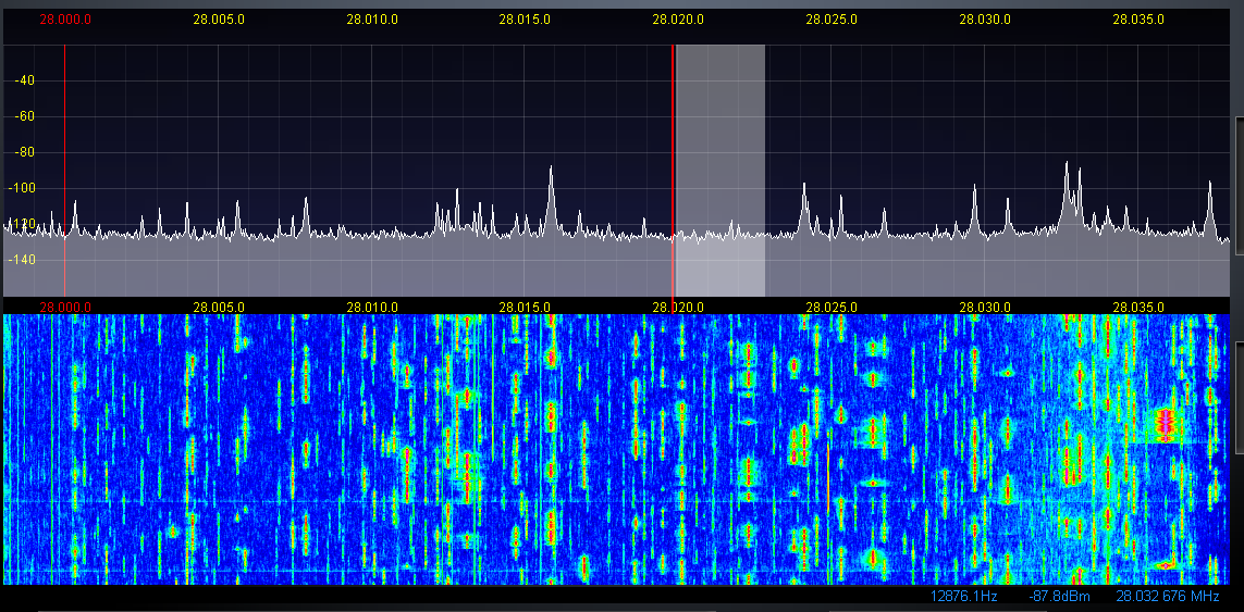
ARRL contest on 10 meters (28 MHz)
Objective: For Amateurs worldwide to exchange QSO information with as many stations as possible on the 10 meter band.
Date and Contest Period: Second full weekend of December. Starts 0000 UTC Saturday; ends 2359 UTC Sunday (December 14-15, 2013)
The following picture shows CW stations during the contest (in waterfall).